
A long time ago I ordered a new 37-key Doepfer keybed and cable from in the USA. In fact I think Doepfer gets them from in Europe so there might be a better way to obtain one. The new keybed is make/break (velocity sensitive) style, but the Pro One does not have the pinning to make use of the break contacts, so I only used the make ones.
Long story short, after making a new cable out of the supplied Doepfer/Fatar one and a 16-pin DIP, my Pro One keyboard is like brand new! The new keybed will fit in the Pro One, but the hole pattern on the bottom of the synth need to be drilled. This is fantastic news for anyone that has the membrane style Pro One keyboard. Anyway it will work with either the original Pro One CPU or my new TurboCPU. I have a couple of photos, but will also upload a wiring pinout later when I get time.
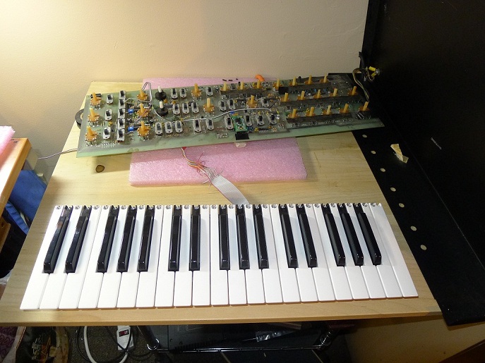

pinout for the Fatar 37-key matrix to the Pro one DIP connector

I’d love to get a new keyboard too.
Sounds like you are close to a full reproduction of the Pro One!
Cool!
Good News.
Is this keyboard ever going to be for sale? It’s just what my Pro-One needs
Anyone can buy it. I got mine from Analog Haven in the USA, but I imagine there are other (better?) places to get it. I just bought the one for myself to fix mine. I wasn’t planning on buying and reselling them. Any tech could do the installation.
Hi is it possible if you can post the pinouts for the connections?? I’m going to make a new cable and connector so was just wondering if you can help.. I have the schematics but just thought I’d ask..
Cheers
DD
I have a photo of my marking on the schematic so I will post that. I have not had time to do a detailed writeup yet though. It still works great! I love it.
Ok please do post ur pin out pic?!?!?
Cheers
Doug
I finally found the pic and posted it.
Bliss!! Thanks
Where we’re you able to find a male to the fatar ribon connector?
The cable came with the keyboard… or I should say that I ordered it that way. I got it as a set from Analog Haven in the USA. Took about a year to get it though. I’m sure there are better ways to get it. Doepfer sells it too, so anyone that sells their stuff will have it as well. It’s probably a standard connector, but I don’t know what it’s called. Some type of insulation displacement header. I don’t recall any marking on it.
Do happen to have the product #?
This is where I got it (including the cable):
http://www.analoguehaven.com/doepfer/mke/
Hello
Are these J wire keyboards for the Pro one still available. Checking the doepfer
site shows them unavailable and it also looks like they were not j wire types. Thanks
They are not J-wire, they are the new type that almost everyone is building into synths these days (with the possible exception of the giants Yamaha and Roland who I imagine make their own). I’m not sure what the technology is called but I think it’s a light gray rubber strip with domes. To be honest I never really looked that close at it. Anyway it’s not J-wire and it’s not membrane.
Getting them is another matter. I’m not sure who all sells them. I’m pretty sure Fatar makes them. It might even be cheaper to buy some used controller and gut it for the keyboard part?
You could try these guys maybe or contact Fatar directly:
http://www.midi-store.com/Fatar-Studiologic-mid-26-p-1.html
I found a Studiologic CMK-137 for this mod. It’s a 3 octave Fatar keyed, and looks exactly like the ones that used to be sold by Doepfer. I’m going to try this mod, and will let you know how it works. Hopefully a cheaper option (I got mine for less than $20 USD) for those of us wanting to upgrade our beloved Pro-Ones…
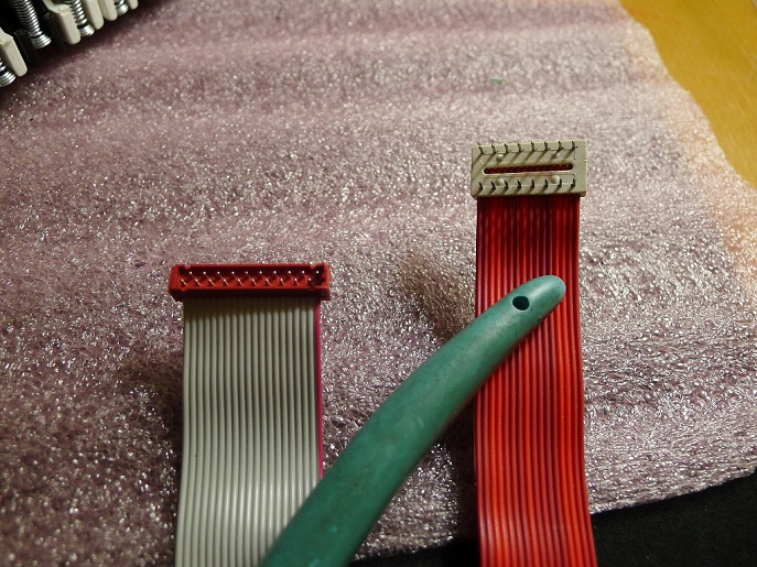
Update, and some frustration: the CMK arrived and I liberated the keyboard. It will fit, but the connector is a 16-pin Micromatch (like the one grantB4 shows on the left above) – I’m trying to wrap my head around how just 16 connectors will cover a 3-octave keyboard along with the Make/Break connections (it’s velocity sensitive)… Finding a schematic on the web has been impossible as Fatar’s site is password protected. Any ideas here? Also, are the pinouts on the Micromatch counted sequential or counterclockwise? Thanks!
Update 2, and some hope! The bottom of the keyboard shows a daughtercard (pic here: https://dl.dropbox.com/u/545852/daughtercard.JPG), and removing it shows a 20-pin Micromatch connector (pic: https://dl.dropbox.com/u/545852/removed.JPG) – I knew I was missing something… I now have to either find a 20-pin Micromatch cable, or desolder the connector from the daughtercard and wire it directly to a 16-pin DIP as grantb4 shows above. As a nice bonus, the card also shows that the pinouts are sequential (look at the bottom of the daughtercard pic linked above). This just might work… : )
Was my wiring photo helpful? Of course the keys are arranged in a matrix (see the original Pro One schematic). Also you can’t make use of the break contacts, only the make ones.
If you search Micro Match Connector on eBay there is a guy in the UK selling 3 right now.
Your mod was the instigator of this – I have a j-wire keyboard, and was getting tired of having to clean the contacts constantly, and have been thinking about a solution for years. Your wiring diagram has been a huge help!
I’m in the US, and can find the connectors from Mouser Electronics, so that’s not a big issue. I had hoped to find a pre made 20 pin Micromatch jumper cable on the web, but no luck. The Midi Store (from your link above) has them, but they are the new black connectors, not the (old) red ones.
I’m either going to have to get ribbon cable and a connector, or may just go ahead and disassemble the keybed, desolder the Micromatch connector, and hardwire the 16 conductor ribbon that came with it to the 13 appropriate connections, and then to a 16-pin DIP header. Disassembly would allow for a good cleaning of the keybed, but the connector route would probably allow for easier servicing in the future. Still on the fence as to what is better…
Again, I’ll keep you updated to progress, and hopefully have this up and running soon. I’m documenting everything – hopefully will make it easier for other to to this.
Cheers, and thanks again!
This is probably the same keyboard:
http://www.keyparts.co.uk/shop?page=shop.product_details&flypage=flypage.tpl&product_id=74&category_id=8
I am planning on doing the same modification. I have the Pro One with the “membrane” keybed and it’s horrible. Love this synth, so am really anxious to have it firing on all cyclinders soon. Can you please post any other photo’s of your work…ribbon cable results, how you mounted it to the chasis, etc. Just anything about this mod. It’s the ultimate solution for resurrecting the classic Pro One. Thanks so much for sharing this.
Make sure you “view” the photos shown on this page. The photos are much larger than appear in the blog format.
Grant can I double check your schematic connections from the 20 pin to the 16 pin cable:
20 Pin 16 Pin
1 16
3 2
5 15
7 1
9 14
13 3
14 4
15 5
18 6
16 7
17 8
19 9
20 10
not used not used
2,4,6,8 11,12,13
10,11,12
This is how I am reading your schematic. Can you please correct me if this is wrong. I’ve hooked everything up this way on the new keyboard and only get the sequencer to work. Thanks, Pat
Yes, that appears to be correct. What is not clear is which pin is pin 1 on the DIP end. It’s confusing because the socket is on the opposite side of the PCB than normal. I can “buzz” it out this weekend when I have it apart for other work. The other thing you can look at in the meantime is that the various CPU pins are making contact as I have marked them on that diagram as well.
Here is a link to the wiring diagram I made for this project – it might help (or, someone might find a mistake on my end…) 😀
https://dl.dropboxusercontent.com/u/545852/P1%20Wiring%20Diagram.png
That is a beautiful wiring diagram. Really easy to follow. Helped me to correct a mistake I had made. I had assumed that the 20 Pin dip was alternating between pins sequentially (like this; 1, 20, 2, 19, 3, 18 etc) which is what the 16 Pin Dip does (16, 1, 15, 2, 14, 3) when in fact the Keyboard 20 Dip pins are in sequential order (1, 2, 3, 4, 5….). So when I was running wires from what I thought was Pin20 (keyboard) to Pin10 (PCB) I was actually hooking up Pin 2 to Pin 10 (wire 2 and wire 13). So now that I’ve got that straightened out, I’ve got no connection between pin 2 and 10 because pin 2 is not used (along with 4,6,8,10,11,12 on the 20 Pin Dip) and the actual connection is Pin 20 to Pin 10 which are wires 20 to wire 13. Can you confirm that the wires coming out of the 20 Pin Dip are in sequential order just like the pins (so that Pin 1 would be wire 1, Pin 2 wire 2, Pin 3 wire 3, etc) and that the pin/wire config on the 16 Pin Dip looks like this: Pin 16- wire 1, Pin 1- wire 2, Pin 15-wire 3, Pin 2-wire 4, Pin 14-wire 5 etc. Why I ask is because hooking pins together requires the correct wires soldered. I know your hooking Pin to Pin but it’s done by wires, so my bottom line is should the wire connections from 20 Dip to 16 Dip looks like this: wire 1 (being Pin 1) to wire 1 (being Pin 16), wire 3 (being Pin 3) to wire 11 (being Pin 2), wire 5 (being Pin 5) to wire 3 (being Pin 15), wire 7 (being Pin 7) to wire 2 (being Pin 1), wire 9 (being Pin 9) to wire 5 (being Pin 14), wire 13 (being Pin 13) to wire 6 (being Pin 3), wire 14 (being Pin 14) to wire 8 (being Pin 4), wire 15 (being Pin 15) to wire 10 (being Pin 5), etc. Anyway, after doing this I only got three keys to work-E, F, G in 1st octave…uggh. Something is still off and I am stuck again. But something is right too for even 3 keys to work. I am wondering if the connector on the 20 Pin ribbon is just not good. Any advise, help , confirmation is appreciated. Thanks, Pat
I had a laptop crash so I don’t know if I can find the rest of the photos or not, but keep in mind that the DIP cable on the bottom of the Pro One exits toward the rear of the case. If I get a change today I will see if I can get more detail together.
Here are a couple of diagrams that might help. I would ignore the pin numbers for the most part and just go with the orientation as shown. I didn’t get all the pins on there, but hopefully it’s enough to establish the pattern.
pic 1
pic 2
pic 3
Grant that is extremely helpful. Any way you can just list where the remaining pins 5,6,7,8 on the 16 DIP connect to on the 20 pin DIP? I am just not seeing the pattern that would allow me to complete the last 4 of the 13 connections.
I was getting the MicroMatch pin configuration from my pic above (https://dl.dropbox.com/u/545852/daughtercard.JPG) – if you zoom in on the bottom, you’ll see it shows a staggered layout with pin 1 to the bottom right, and pin 19 at the bottom left.
Yes, I see what what your saying now. However for wiring purposes it really just moves in a sequential way from (using your photo) right to left. I was more worried that it may be like the 16 Dip config where it goes from 1 to 16 to 2 to 15, etc. Still trying to find the last 4 connections from Grants latest “pic 1”. He shows it all except for 4 connections from the Dip 16 (pins 5, 6, 7, 8) to the Dip 20. Just need those to start soldering.
Thanks, Pat
Ok, I’ve figured the pattern out but it only works if the 20 way IDC connector is moving from pin 1 to 20 by non sequential Pin numbers (1, 20, 2, 19). So, I’ve now hooked up all the wires following the correct Pin connections from the schematic and matching the wires of each pin to the correct wire of each pin on the other DIP and all I get is two notes to play. More and more I am convinced I must have a bad ribbon connection. Any place to buy a non-plastic male 20 Pin ICD connector?? This red plastic one is cheap and flimsy!! Thanks, Pat
I haven’t had a chance to complete the pinout, but I wouldn’t over look the DIP end. On mine every second time I plug it in I have dead keys and if I fiddle with the DIP it starts working. I’ve also replaced my DIP socket which helps alot too. My DIP cable (plug) is old and that’s the part that is causing problems.
Interesting. Are you soldering a new male onto the PCB (with ribbon attached) or installing a female then getting a new male and attaching 16 wire ribbon cable to it? Could I ask where you got the DIP (male, female, or both)? Thanks
I still haven’t gotten around to actually creating the cable (work, school, new baby – nothing major…) so I can’t say whether it works or not. I was planning to just desolder the ribbon cable from the 20-pin MM and resolder the legs to the 16-pin DIP header I picked up with some 28 AWG wire. This way I would save the original cable if it didn’t work properly.
All the MM connectors I found seem to be designed to ‘press on’ with ribbon cable or solder directly to a circuit board. I did see this, which might work with some cutting/stripping:
http://www.newark.com/te-connectivity-amp/1483358-3/micromatch-20way-250mm/dp/98K5752?in_merch=Popular%20Cable%20Assemblies
I got my new cable with the 20 pin Dip and attached it to my keyboard and then soldered the wires to the 16 pin Dip ribbon cable from the PCB. The new 20 ribbon cable actually firmly clicks into place on the keyboard which was nice to hear. However only 16 keys are now working. There is definitely a pattern to what’s working and what’s not working based on your matrix schematic. The working keys are (starting from lowest ocatave to highest) are C, C#, Eb, E, Ab, A, B,C,E,F,G,Ab, C, C#, Eb, E. The other odd thing is the tones seems to be in reverse now…high notes are at the low octave and low tones are at the upper octave!!! The pattern on the matrix made by the working keys shows that entire rows work (except the last note on each row) and entire rows don’t work. Any suggestions?
Got er Done….turns out the 16 Pin dip started with the 16th pin as the Red wire, then counted 1, 15, 2, 14, 3, etc. That changed the wire connections and that fixed it all up. Right now all keys are working but they all make the same tone sound. I am taking this to mean that calibration is left to be done? The manual walks you through this but if anyone has any tricks, tips, shortcuts or lessons learned doing a calibration I am all ears. Thanks
Do you have a voltmeter or an oscilloscope? Or maybe even a logic probe? If you look at the 6 bits of data going into the DAC, you should see the binary values increase as you go up the keyboard. Then of course, you should also see the analog voltage on the output of the DAC change accordingly. If memory serves, the DAC inputs and outputs are held steady until the next key value is applied to it, so theoretically you don’t even need to hold the key down while you measure. You should see changes as you play different keys. I say this because it’s odd that you’d only get one pitch.
Edit: I may be wrong about the inputs being held steady. I don’t have the schematic handy but I seem to remember that the scan lines for the keyboard are shared with the DAC, so the DAC only gets a new 6-bit update when it’s Latch Enable pin is strobed. That means you can look at the output of the DAC with a voltmeter, but the digital inputs you really need a scope to see it (by triggering on the Latch Enable).
Thanks Grant, but it turned out I just needed to turn on the kybd in the Oscillator B section. I then setup the keyboard setting up the manual says to tune the two Osc and the next thing you know everything works!!!!! Thanks so much for all the help.
When you get it back together shoot us a photo!
Not sure how to post a photo here. Do you want me to send it directly to you as an attachment? Will get it done this weekend. Been enjoying the heck out of this thing!!!
That would be great!
I wonder if this guy would sell keybeds? He seems to have a pile of 37 key keyboards!
http://www.supersynthesis.com/pages/super37
Just contacted them and seems like there may be interest in providing replacement keybeds for Pro Ones. Hopefully it works out!
Hi, Jon.
Any update from Super Synthesis? My membrane Pro One is driving me crazy!
Hey JP,
Just sent a follow-up email tonight asking if they had an estimate on when something could be ready. Once I get a response I’ll post here. They were definitely interested, however, so I’m crossing my fingers they release something soon.
Jon
Did anyone contact super synthesis? I bought the CPU update, but failed to grab a key bed when I still had the chance..
Hi,
I’ve recently bought a Pro One with NO keyboard, and I would like to get one!
I’m looking for a replace like the one you stated from Doepfer (and Analog Heaven) but them are not available anymore.
Anyone could help me?
Thank you in advance!
I’m sure the Doepfer one is still available. You might have to find a different seller though. Also you could find some other (cheap) 37 key keyboard controller or synth of approx the same dimensions and steal it from that.
M-Audio made the MidAir series of controller keyboards in a 37-note version. Not sure exactly what keyed is in there, but might be worth scrounging the auction sites for a cheap one.
Uh, I meant ‘keybed’ 🙂
See if you can get the dimensions on it. The width is pretty standard of course, but some of the controller keyboards aren’t long enough (deep enough?) to fit all the way from the front of the Pro One to underneath the case. I’m sure they could be made to work though, just would look ugly.
There’s one down at the local Pawn Shop – I’ll see if I can get some measurements of the keybed.
While I’m here, I’ve taken the keys off of the Studiologic keyboard I bought, and found the Micromatch connector is exactly 20-pins. I’m going to desolder the connector and just hardwire from the solder points to a 16-pin DIP header. Can you confirm that the connectors on your keybed are numbered from pin 1 at the top left and numbered sequentially clockwise with pin 20 just below pin 1 on the bottom?
Oh – some pics of what I was asking:
https://app.box.com/s/yl0ccwyahjm3n9tmabor
And what I will be connecting:
https://app.box.com/s/le55skfg18qi4smlkpj7
Hard to say if that keybed would have the same pinout on the connector or not. It’s really the Pro One DIP that requires the (non-velocity) pins to be connected (the makes only) in the order shown on it’s schematic. Might require a bit of trial and error. Even with the fatar schematic and Pro One schematic I had to make a few changes to mine. Anyway, mine is zipped up at the moment so hopefully the photos up top help.
Which Studiologic keyboard are you talking about?
The CMK-137 I mentioned here just over a year ago. Once I pulled the keys off and compared my circuit board to the one you have in your pics they look identical except your has a different connector (mine has the Micromatch style)
Success! The Studiologic CMK-137 keyboard was wired up today and works perfectly!
I took a bunch of pictures (and need to change my wiring diagram I uploaded above) and I’ll drop a link to it all as soon as I annotate everything.
Big thanks to everyone here for the help!
Here’s a PDF of my build:
https://app.box.com/s/8ibr32f2yxqhys7je2kt
If you can find a Studiologic CMK or TMK 37/137 on the cheap it works!
Thanks to everyone here – couldn’t have done it without your help.
Great write-up and lots of details and photos! It might be a bit easier if you can find the mating Micromatch connector somewhere … preferably with a cable attached. I’m not sure where they are used. But anyway great job. I’m so happy with mine as the keys are PERFECT now and I don’t think it’s possible to get them this good on the OLD original.
You might also want to mention this on Gearslutz as there was a thread there about it too at one point.
I searched the Internet for anything like a preexisting Micromatch cable and could find nothing… Those connectors are designed for quick connects from board to board (like the CMK) or for other internal components. Hardwiring was the only option I could think of other than maybe getting a surface-mount 20-pin connector like the one on yours. Oh well, it’s done now and works like a dream – you are so right about never wanting to go back to the old one.
I’ll go look this up on Gearslutz and drop some info. Thanks again for the help!
Just wanted to say thanks to all here for the info, especially Grant and PDN; I just found a StudioLogic CMK137 (wasn’t easy to find, nor as cheap as you got PDN!), and so will be using the PDF above to help guide me…
PDN. Grant and whomever else is following this – does this seem like the correct Micro Match connector for the StudioLogic board? I’m thinking this plus some ribbon cable should make the job easier, rather than desoldering the existing connector, etc?
http://www.digikey.com/product-detail/en/2-215083-0/A111124CT-ND/4142508
Yeah, looks about right. I would get several in case you make a few mistakes. It takes regular ribbon cable.
Just wanted to share some pix of my finished product – came out fantastic! Many thanks to Grant and PDN – https://flic.kr/s/aHske38Ru7
Of note, I used the Micromatch connector from Digikey I linked to above, and it worked perfectly. So no need to remove the keys on the keyboard as outlined by PDN…
Looks great!
I guess there was no way of utilizing the cable with the micromatch on there already?
(The one visible in the CMK photo … perhaps it’s soldered on?)
No, you can’t use the original Studiologic CMK ribbon cable with the Micromatch connecter on the end, because it has too few connections; the connector on the circuit board that you can see has fewer pins than the one underneath the board, that you eventually need to connect to…
I just bought the CMK-37 (not 137) and the connectors are different. It has 3 x 8pin connectors, label as P0/P1/P2. Can anyone help to figure out the pin assignment to map with the Pro One’s 16 pin socket?
Did you get this sorted..?
Found the CMK-37s in stock!
Didn’t expect it to be so difficult. 37 keys seem to be very out of fashion, doepfer doesn’t do special orders, Fatar are impossible to reach etc etc. But these guys have about 10 of them if anyone’s interested.
http://www.espaceclaviers.com/fatar-studiologic-cmk-37__p5063,oasc,pg0.htm
…although these boards seem to have a very different wiring. There are two 16 pin micromatch connectors/flat cables that attach to a small midi board. Pulling those and testing, I can only get a few keys in the top octave to register at all. But following the circuitboard traces on the midi board I can see that a lot of the pins on cable 1 are connected to the same pins on cable 2. Maybe some of the wiring of the ‘matrix’ shown in the fatar blueprints happen on the midi board in this version.. To be continued.
Worked it out. A bit more challenging than the CMK137, requires trace cutting and soldering of short wires to ‘regroup’ the ‘make’ key groups. Will post pics later!
Any photos of the guts?
Hi guys,
We buy, restore and sell Pro-Ones and have more than one Pro-One with a defective membrane keyboard we’d like to replace. Grant emailed us recently suggesting we check out this thread. We had actually found this page a long time ago and tried to find Doepfer keyboards but they apparently stopped producing them, and tried to contact Fatar to buy several keyboard mechanisms but their web contact page was broken and we were never able to establish contact. If anyone finds a source for good replacement keyboards, we would greatly appreciate an email about it.
Also, by the way, Grant’s CPU replacement is highly recommended!
Thanks!
Mini
See my link above to a shop in France that has another 8 cmk-37s in stock. I haven’t completed my build yet, and these keyboards are a bit more work to get working, as the ‘matrix’ of keygroups don’t match Grant’s schematic. You need to cut some traces and solder on some short wires. Not very hard, if you service Pro-Ones it should be easy! I’d be happy to help out with pics if you go down this route. Note: earlier in this thread someone else mentions getting a cmk-37 too, but he seems to have yet another variation of connectors etc…
Excellent work. It will be so worth it in the end. My original P1 keybed was still “iffy” even after I cleaned it. The new one is perfect.
Just a heads up that I have now completed the electrical part of the keybed replacement and everything works. It’s a dream to play the pro-one now!
Hi Mini, can you provide details about the restored Pro Ones you supply, a web page which provides an email contact ideally.
Doepfer now have and can supply the Fatar 37TP/9S (37 keys), The two I ordered just arrived.
They are likely available now due to the recent demand for this small keybed as some manufacturers are making products with them, one such example is Waldorf’s new kb37 frame for modular units.
Pingback: Sequential Circuits Pro-One – keyboard replacement | techsmechs
This email came in today…
Hey Grant,
I emailed Doepfer about the availability of their 37 note keybeds, they just replied to me with the following:
==============================
We have some synthesizer keybeds 37TP/9S left, but they don’t have suitable contact boards ( only with reversed diodes ) and we are waiting for the right contact boards which should come beginning/middle of December.
==============================
you able to explain what they mean?
Interesting, Doepfer told me they don’t do the 37 key anymore.
“due to low demand the 37 key keybed is no longer part of our delivery
program. We have also stopped the service to procure special keybeds from
FATAR already end of 2012.”
Maybe the demand went up since both I and this person asked about it 🙂
This is what my keybed looks like from the bottom and it was called a TP/9 when I ordered from Analog Haven. See my post near the top. So I’m confused by their comment too. For sure you need the contacts and diodes, but I wonder if they are referring to some additional scanner board or they do mean the single layer (phenolic?) board like I have with the diodes on it. I would be tempted to tell Fatar that this is really all that is needed:
Lars, how did you order the CMK-37? Their website is only in french, and they don´t seem to ship internationally. I´ve tried to contact them via mail, but since I don´t know any french, I had to write in english, and I haven´t received any answer yet
Yeah I couldn’t figure out the purchase process either, so contacted them and in the end paid via paypal. The email I used to talk to them was espaceclaviers@gmail.com. Will try and hook up the keybed to Pro-One this weekend, fingers crossed!
If you haven’t already, check out my blog about how to mod these CMK37s: http://techsmechs.wordpress.com
OK, now I also have ordered two CMK37s from France. My main goal was to replace a damaged keyboard on an Octave Cat, but since I also got a Pro-One the other one will be useful as well. So the things I have to do is to perform the haxx A-I, and then just use the interconnection table? (maybe I should post this on your blog…)
yeah 🙂
I contacted Studiologic and they confirm their CMK137 uses the Fatar TP/7BA keybed.
I recently acquired a Pro One completely missing the keyboard. So obviously, this thread is providing me with some hope in replacing it.
I am really close on this but have hit a wall. I have a TP/9 Keybed that looks identical to the one Grant has pictured above. It included the 20 pin ribbon cable. I built an adapter to convert the 20 pin ribbon cable to the 16 pin dip connector. I have tested the pinout end-to-end and all looks good.
All notes on the keyboard play. The problem I am having is that the notes play out of order. I will try my best to describe it (Starting from c0 and going up the keyboard). The first 3 notes play in order then it jumps down to a much lower register starting with key 4. The next 16 notes play in order, then it jumps up to a higher register where it plays another 16 notes in order. the last two notes jump down to a slightly lower register but play in order. There are keys that play the same note D0 and F#1 for example.
I’ve triple checked the pinout and tested for shorts and everything checks out. Im hoping this keybed is compatible.
Any assistance or advice would be greatly appreciated
The issue ended up being a bad CPU.
Hi Cwrite, you said ” I built an adapter to convert the 20 pin ribbon cable to the 16 pin dip connector. I have tested the pinout end-to-end and all looks good.”
Can you share the details of this adapter?
Thx
Hi Mini, can you provide details by means of a website link of the place where your restored Pro Ones are supplied?
Doepfer now have the Fatar 37TP/9S keybeds available now, my two arrived last week.
Some manufacturers, such as Waldorf (kb37 for modular units) are producing products with these key beds which explains the recent and current availability.
ketracel,
that’s great news! we were just about to track down some cheap midi controllers to gut for their keyboards, but im glad i checked here cause we hate the thought of doing that, even if it means paying more for just the keyboard mechanism! you can find us at tonetweakers.com.
thanks
mini
Hi guys,
Doepfer 3 Octave Fatar 37TP/9S Keyboards seem to be out of stock or discontinued. Pleasse, Where are you guys buying them?
Thanks in advance!
hey guys,
so we get all excited cause we thought we’d found a great source for brand new cheap replacement keyboards…
guitar center carry the ik multimedia irig pro 37, and they’re occasionally on sale for only $80. our tech was pretty sure that he could rig this keyboard up to replace the pro1 membrane keyboard, even though it’s not a fatar keyboard mechanism. however, we just bought one and the feel is horrible, plus there is literally an empty space of approximately 1/4″ in front of the black keys. we didnt even bother to open it up to see if the modification was feasible. so now we’re back to looking for another cost effective option for replacement keyboards for our later pro-one (and other vintage synth) restorations. we contacted the US doepfer supplier and he says they’re not supplying them anymore. we tried to email fatar, but the website email address was no good. we tried getting in touch with a couple other manufacturers who use 3 octave keyboard mechanisms but got no reply. if anyone’s got a good source for reasonably priced new replacement keyboards (preferably fatar), please get in touch with us through our website (tonetweakers.com).
thanks
mini
Synthax.de sells 37 key fatar keybeds! I bought 4 of them 🙂
Finally, some good news!
I don’t see them on their website. How did you order them? Do they use the single connector as Grant describes here? Thanks!
I was wondering the same thing.. plz respond!
Thanks to Grant and everyone for this great thread! I just finished installing the Fatar keybed in my membrane equipped Pro One. It works great and what a difference.
I was unable to locate the keybed new form any of the sources listed but I did remember the older Novation Remote 37 SL and that it had a Fatar. I found one on ebay and as luck would have it it’s the same as Grant has. It even comes with the ribbon cable.
There’s another one ending soon on ebay.
http://www.ebay.com/itm/NOVATION-REMOTE-37SL-ELECTRIC-KEYBOARD-WORKING-/282370156082?hash=item41be92a632:g:5yMAAOSwB-1Yrcpy
http://techsmechsvintagesynth.com/home/tm-2%20pro-one%20keyboard%20replacement%20kit.html
Hi Charles,
That’s great news. I also have a keybed from a Novation Remote 37 SL and will be adapting it using parts from techsmechsvintagesynth.com. One end of the keybed ribbon cable will need to be modified it seems.